In this fourth and final entry of the series I will discuss bushing work, re-assembly and finally, testing and mounting the movement back into it’s case. Part I of this series can be found here, Part II here and Part III here,
Once the pivots are inspected, cleaned and polished it is now time to install any bushings required as result of careful inspection.

I acquired a Bergeon Bushing Machine in the spring of this year (2016). As I mentioned in Part III, some may prefer to bush by hand which I think is commendable but I have decided to go the bushing machine route. In the last few months I have been using and learning its many tools. It comes with a set of chucks and reamers some of which (right side rear) are a bit of a mystery to me. I cannot see using any of the large reamers any time soon though I assume that if I am working on tall-case clocks which have larger movements they would come in handy.
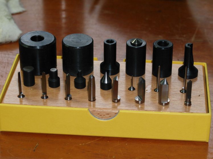
First is selecting the correct bushing using a micrometer to measure the diameter of the pivot. Then, I select the proper bushing from my Bergeon assortment kit.

The bushing I have selected for the escape wheel pivot (measured at 1.46 mm) has a depth of 2 mm, an outside diameter of 3.5 mm and a pivot hole of 1.5 mm. In the next photo I am positioning it on top of the 3.47 mm. hole that I have just just “drilled” using one of the reamers. The outside diameter of the bushing is slightly larger allowing for a tight friction fit.
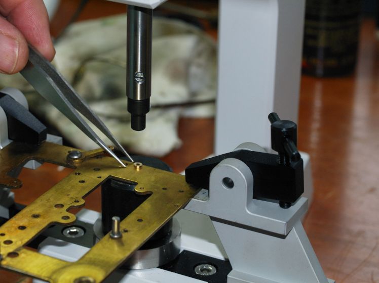

Once I have selected the correct bushing I test it on the pivot for fit and then I position it over the pivot hole and use a small hammer with it’s nylon end to tap the top of the bushing machine centre shaft lightly until the bushing is properly seated and level with the plate ensuring that the oil sink faces the outside of the plate.

To check proper fitment of the motion works bushings/pivots, I assemble all the wheels on that side (both plates), check for a smooth action and determine if any additional reaming/smoothing is required. I do the same for the strike side.
Once all the bushing work is completed and I am satisfied that each bushing fits correctly and operates smoothly, I re-assemble the mainsprings, wheels and levers and then re-attach the back plate using the five plate screws. We each have our own method of re-attaching the back plate but I work from the bottom up, that is, from the mainsprings. Once I have the mainsprings in place I immediately install the bottom 2 plate screws (loosely) and then work from the motion works side to the strike side using a pivot locator tool, if necessary, to coax the pivots into their respective holes.

Positioning the various levers can be a bit frustrating because those that have helper springs seem to slip out of their pivot holes easily as you are putting the plates together. Perseverance is certainly the key.
The one difficulty I had was adjusting the synchronization of the count and drop levers, that is, getting the drop lever to sit in the cam while I adjusted the locking lever position. The clock must be completely assembled at this point and once together loosen or take off the nearest pillar nut and pry the plates apart to take out both the flywheel and the locking wheel. Once out, the locking wheel can be re-positioned by moving the pin on the wheel so it rests on the locking lever. Once this is completed, re-install the flywheel. This is basically a trial and error process and I never seem to get it right the first time.
My only error in the first go-around was not restraining the strike mainspring during this procedure. While spinning wildly the strike mainspring flattened the protrusions off the cam that allows the hammer strike. Momentary panic! Once bent back into shape everything was fine. Naturally, I secured the mainspring for my second successful attempt.
My reference for these adjustments is Steven Conover’s Striking Clock Repair Guide which is an invaluable guide to striking American clocks.
Once the parts are re-assembled it is on to the final testing phase which takes days (and weeks, perhaps) as the clock is being carefully regulated. The following video shows the movement on a test stand (in this case, Gene’s Test Movement Stand). The sound of the pallet on the escape wheel is very quiet; you are hearing other clocks in this room. The clock is in beat and in the video you can see the movement of the escape wheel from various perspectives.

Once testing and regulating is completed and I am satisfied the clock will run reliably for 8 days I return it to it’s case. There are only 4 mounting screws. You may have to re-position the coil gong by loosening the adjustment nut on bottom of case to get that satisfying strike sound.
This attractive little Sessions American No. 2 time and strike mantel clock has now been serviced. It required 5 bushings and should run reliably for the next 3-5 years.
Discover more from Antique and Vintage Mechanical Clocks
Subscribe to get the latest posts sent to your email.

You must be logged in to post a comment.