Seth Thomas is a well-known American clock manufacturer with a long history, and they produced a variety of clock movements over the years. The Type 89 movement is one of the many clock movements produced by Seth Thomas between 1900 and 1938.
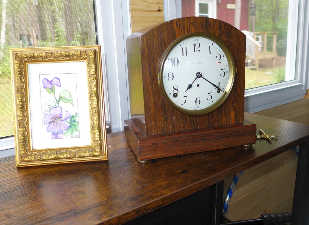
The mantel clock in question features the Type 89 movement. Acquired in the summer of 2023, this clock boasts a simple and straightforward design.
In the first part of this two-part series, I discussed the disappointments I encountered with the clock’s case.
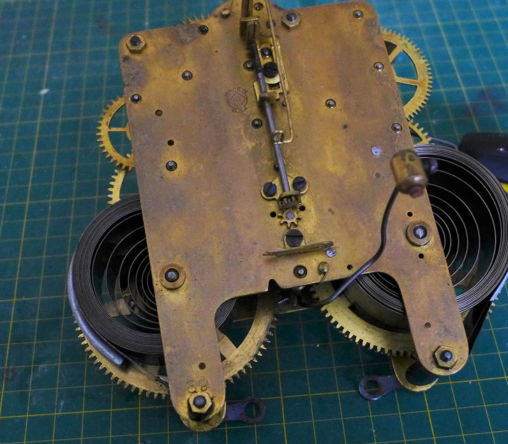
The focus then shifted to the disassembly process and my examination of the widely-used Seth Thomas Type 89 clock movement.
My observations highlighted a replaced mainspring on the strike side, the necessity for bushing work, and indications of rust, all of which posed challenges that I committed to addressing in subsequent stages such as cleaning, bushing, oiling, and reassembly.
The focus of this blog post is the completion of servicing of this type 89 clock movement.
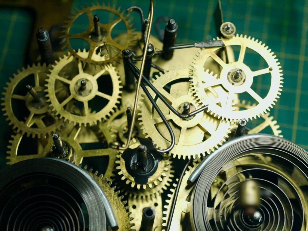
Cleaning of the mainsprings
There is always the temptation to do nothing with the mainsprings if they look acceptable. However, cleaning the mainsprings is an essential part of clock servicing. Uncoiling and wiping the dirt and grime from the mainsprings with a cloth is the preferred method, but cleaning them with an ultrasonic cleaner is also an option.
In Part I, I cleaned the mainsprings in my ultrasonic cleaner and provided a rationale for this decision. Before I go any further, I’d like to emphasize a crucial point regarding the cleaning of mainsprings in an ultrasonic cleaner. This practice is not recommended and should only be considered as a last resort.
While cleaning mainsprings in an ultrasonic cleaner has little impact on the surfaces or mechanism of the cleaner itself the oil removed from the mainsprings generates a black liquid that contaminates the cleaning solution, rendering it ineffective for future use.
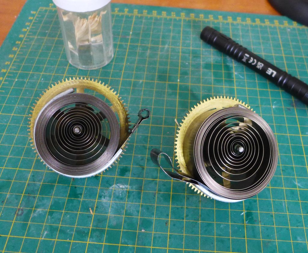
Clamps have been applied to secure the mainsprings after oiling, and they’ve been set aside. Now, we move on to the next step: the bushing phase.
Bushing the movement
As the movement is fully disassembled this is the stage where bushing work can be done.
I commend individuals who choose to bush by hand, but personally, It is not for me.
Various systems exist for bushing, with KWM and Bergeon being the two most widely adopted. It’s worth noting that neither system is inherently superior to the other, as preferences tend to vary among enthusiasts. When referring to a “system,” it’s important to understand that the bushings from one system are not interchangeable with those from the other.
That said I use the Bergeon system.

Before bushing, I identify all the locations requiring attention and mark them with a Sharpie. There is no permanent mark as rubbing alcohol will easily remove all traces of ink.
I have an excellent assortment of bushings and have all the required ones for this project.

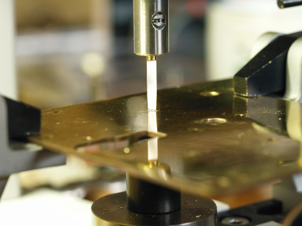
Using cutters each hole is drilled out and chamfered, that is, removing the sharp edges to allow the pushings to be pressed in smoothly. As I insert each new bushing I test the fit by assembling the wheels to check how freely they move. This allows me to make small adjustments in the event the pivot is too tight in the bushing hole.
Based on my initial assessment, the bushings for both the front and back plates of the escape wheel were the most worn. The next new bushing is the fourth wheel front plate, the one adjacent to the escape wheel. After three bushings everything looks good and the wear further down the train does not look too bad. A fourth bushing for the fourth wheel should be enough.
A cutting broach is used to enlarge any holes that are a tight fit for a pivot followed by a smoothing broach. To prepare for the wheels to go back in place all bushing holes are cleaned with pegs/toothpicks.
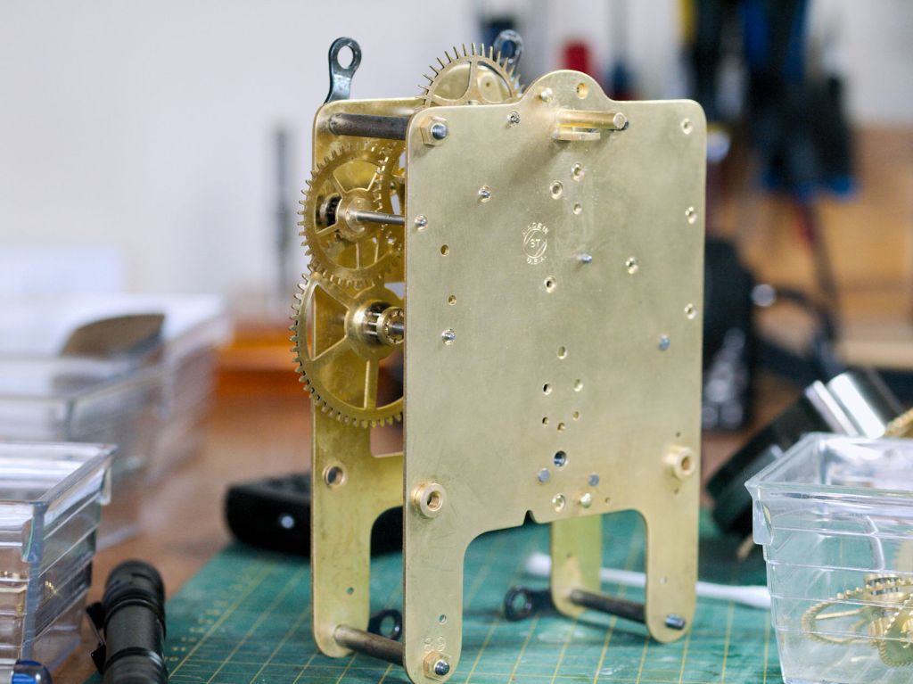
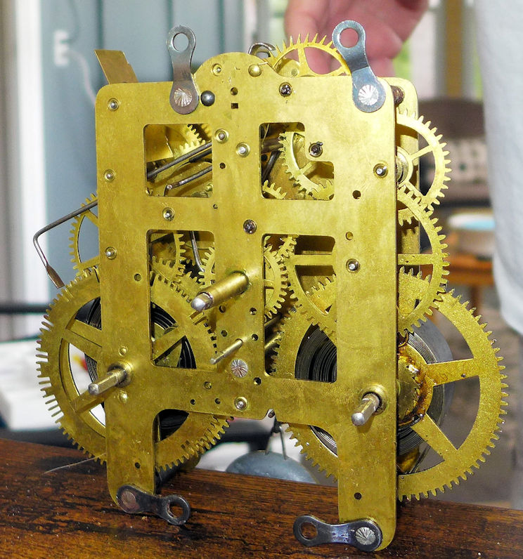
In the photo above, the plates and gears look shinier after a session with the ultrasonic cleaner. However, it’s important to note that the main goal in clock repair isn’t to make everything as shiny as possible. The focus is on reducing wear and tear. Some dirt and grime on the plates might not come off completely during the cleaning process in every case and it is not something the clock repairer should be overly concerned with.
Back to bushing. There is a little bit of play on the second and third wheels but it is tolerable so, I think I will stop at this point.
Were I in the clock repair business I would bush everything on the time train, or the entire movement for that matter, but since I usually inspect movements in my collection every 2-3 years I can address any additional wear at that time.
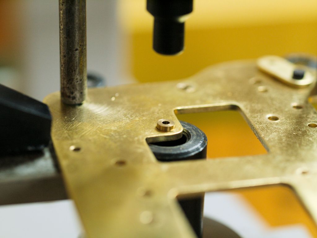
On to the strike train. In the first article, I mentioned that there was not much wear on the strike side which might be attributable to that side not being wound as often. The only hole that must be addressed is the cam wheel bushing on the front plate. Why this bushing hole is worn much worse than the others is a bit of a mystery.
Okay, all the work is done for a total of five new Bergeon bushings. The holes have been pegged, and the movement is now ready to be reassembled.
The one hiccup encountered during the bushing process was the malfunction of my caliper tool. Fortunately, this isn’t a major problem, as all the Bergeon bushings are uniform at 3.5mm outside diameter, with inside diameters of either 1.4mm or 1.5mm so I knew what size to grab first.
Reassembly
When dealing with American 8-day time and strike movements, there are challenges in configuring the strike mechanism accurately. Occasionally, luck is on my side, and I manage to place the paddle in the deep slot, position the lever in the lowest part of the cam wheel, and align the warning wheel just right on the first attempt.
A useful tip. If the lever is in the lower part of the cam wheel and the paddle is not in the deep slot, simply move the toothed count wheel sideways so that it does not engage the pinon and reposition the wheel till the paddle finds the deep slot.
No luck setting up the strike this time! If the strike train does not lock correctly it will simply keep on running and you will know that soon enough.
The plates can be partially pried open without the risk of all the wheels and levers springing out. Repositioning the warning wheel involves moving the fly aside, carefully extracting the 4th wheel from its pivot hole, and rotating it a quarter turn or so to ensure the warning pin aligns with the stop lever.
A minor issue with the hammer lever surfaced as it was not aligning correctly with the strike pins on the cam wheel. No disassembly of the movement is required for this adjustment. Simply loosen the bottom two nuts by the mainsprings, and the strike hammer can be removed to straighten it. After having been bent multiple times over the years, straightening it out resolved the issue.
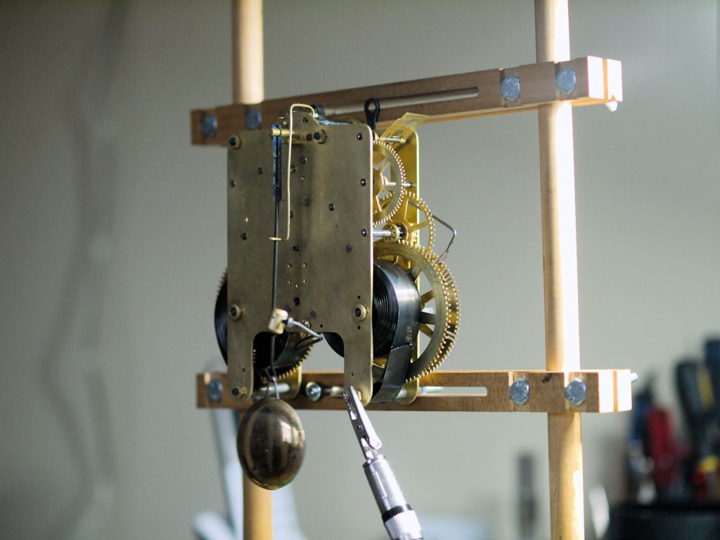
Next, the movement is oiled with Keystone clock pivot oil and mounted on a test stand. After a week it is running and striking as it should.
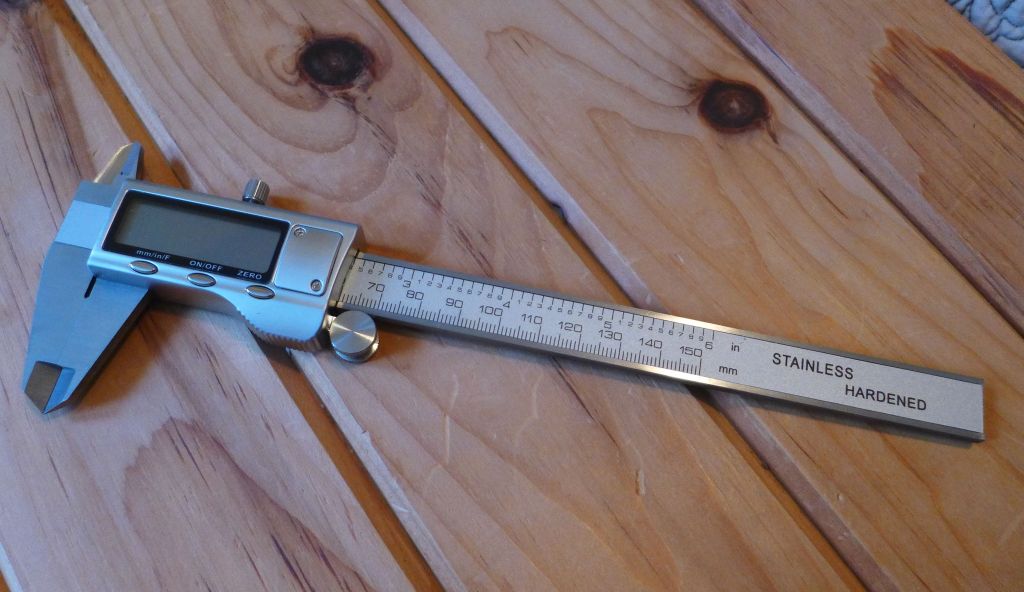
And lastly, my new caliper arrived just as I was concluding the servicing on this clock.
Addendum
To properly configure the strike side, pay attention to the positioning of the levers as pointed out by the arrows.

In the above photo, the lower arrow shows the paddle in the deep slot, and the upper arrow shows the drop lever in the indent of the cam.
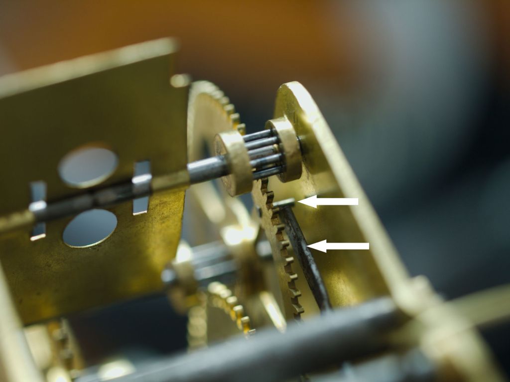
The upper arrow shows the position of the stop pin on the stop wheel. The lower arrow shows the locking lever.
Discover more from Antique and Vintage Mechanical Clocks
Subscribe to get the latest posts sent to your email.

Excellent presentation. Would like close up of the setting up the striking .
LikeLike
Thank you. I have added two photos to the article showing how to set the levers on the strike side.
LikeLike