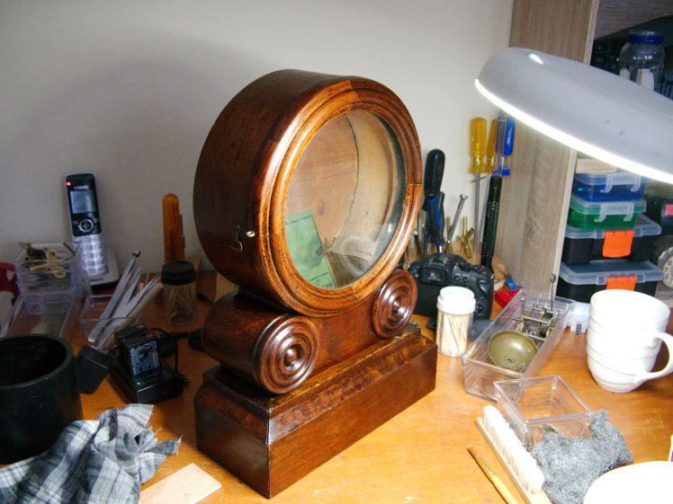
After having completed work on the case and dial pan of the Ingraham Grecian time and strike shelf clock it is now on to servicing the movement.
Assessing the movement
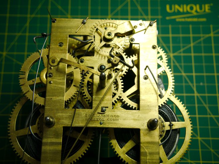
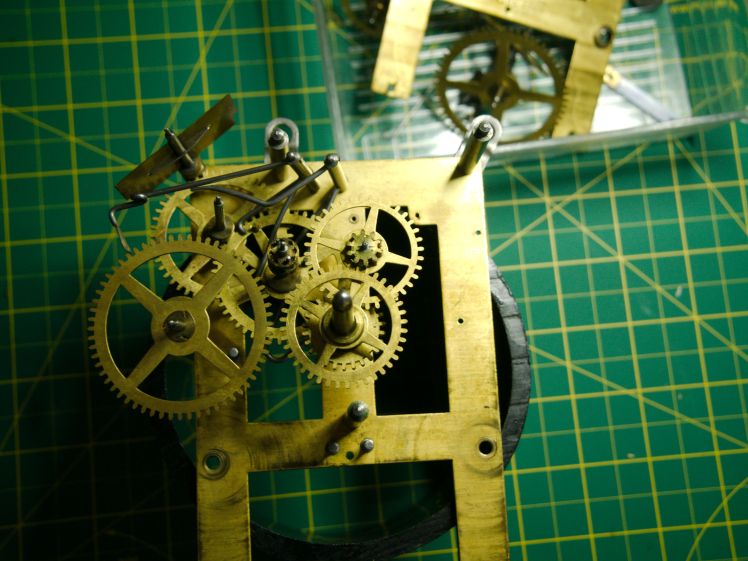
The movement is in surprisingly good condition for its age. It has been serviced in the past, when, I don’t know. Here’s what I discovered during the inspection.
- In an early servicing, 3 bushing holes were punched. Many years ago clock repairers used a punch to close pivot holes that had elongated after years of wear and it was considered an acceptable practice at that time. Not today!
- The mainsprings and alarm spring appear to be original and the alarm mechanism showed no evidence of wear.
- At a later point a clock repairer installed 3 brass bushings, 1 on the front plate and 2 on the backplate.
- Pivots had been replaced on one end of the warning wheel and one end of the third wheel time-side.
- The thin brass strap that trips the alarm has been re-riveted.
The repairs were neat and professional.
But there were problems
While there were some decent repairs, someone attempted a homemade fix and it became a non-working clock. I suppose that is to be expected from a clock that is 149 years as it passes through several hands.
It appears that the clock was eventually passed on to someone who had little knowledge of things mechanical. It might have been simply out of beat and an attempt was made to adjust the crutch by twisting the crutch loop around the pendulum leader. I can only assume that in their attempt to access the mechanism to “fix” it, the dial and brass bezel were damaged in the process.
Without impulse the clock would run a minute and stop and would never run in that condition.
I reshaped the crutch loop and bent the crutch slightly to achieve a healthy beat and the clock began to run.
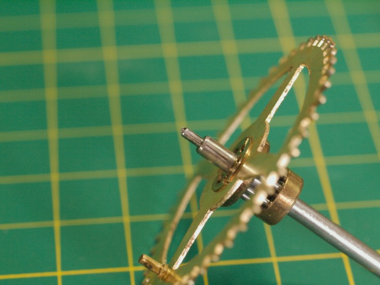
While the clock was running I discovered a bent escape wheel tooth. It was running despite this issue, but the verge would occasionally skip the bent tooth. A bent tooth is often the direct result of transporting a clock without removing the pendulum bob.
Servicing the alarm
There is not much to the alarm mechanism. Three pins hold the 2 small plates. I doubt this alarm was used much, It was taken apart, parts cleaned in the ultrasonic, reassembled and oiled.
Servicing the movement
After letting down the mainsprings and disassembling the movement the first order of business is to straighten the bent escape wheel tooth. The trick is to “draw out” the tooth out with a pair of smooth flat jawed pliers. It is important not to stretch the tooth as this will introduce other escapement issues. Unbending the tooth is a simple procedure but a disaster if things go wrong.
Next is the inspection of pivots, lantern pinions, wheel teeth, arbours, cut pinions, of which there are two in the motion works. All looked good. The gears were meshing well on both time side and the strike side.
Following the inspection is parts cleaning in the ultrasonic machine. Once the parts are dry I inspected the movement more closely for any issues I might have missed. Next is polishing the pivots.
Once the pivots are polished it is time for bushing work if required. In the case of this movement 2 are required for the front plate and 3 for the back. On the backplate, one of the bushings is the escape wheel bridge.

There were two other pivot holes that were iffy and okay for now but since I am keeping the clock it will be inspected in 3 or 4 years for wear.
Reassembly comments
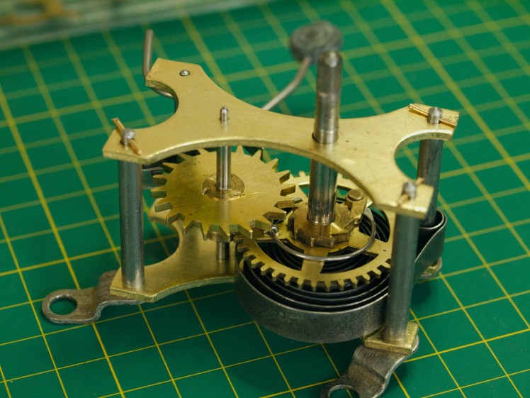
The third wheel on the strike side is a combined locking and pin wheel with 2 locking pins and 2 hammer pins. There is no cam, unlike many other American movements. The spaces between the pins allow for the drop lever to descend.
The fourth wheel is the warning wheel only and it is not used for locking.
Unlike later Ingraham movements that have a passing strike on the half-hour, this is an hour strike only.

The count wheel is advanced by two protruding pins on the third wheel lantern shroud, another unusual feature. It is important to ensure that the count wheel is firmly in place, not loose but not too tight, so the third wheel pins can advance the count. The stiffness can be adjusted by bending the brass clip on the count wheel.
During reassembly, the warning wheel is set about half a revolution to prepare for the strike. Also during reassembly one of the two lock pins is placed on the locking lever, the end of which has a hook. This is to permit the count lever to go into one of the deep slots.

Sometimes it takes a couple of tries to get it right. Usually, I must make an adjustment or two after the plates are together but I was lucky the first time.

When I finished servicing the movement the new hands arrived from a supplier. So, here it is with new hands attached and the movement back in the case.
The clock has been returned to its former glory.
Discover more from Antique and Vintage Mechanical Clocks
Subscribe to get the latest posts sent to your email.

I encountered the same protruding lantern pinion pin drive of the count wheel on a Seth Thomas #44 ‘hip’ movement. The count wheel teeth had one straight side and one concave side to clear the driving pin. First time for me too.
LikeLiked by 1 person
In my beginning years of clock repair, I had no clue how they functioned. Since then I come across the protruding pinions from time to time.
LikeLiked by 1 person
Ron, Thanks for sharing this.
LikeLiked by 1 person
Thanks.
LikeLiked by 1 person